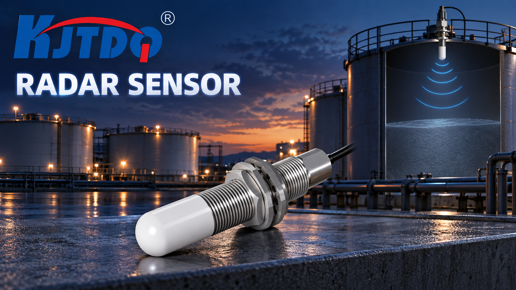
A radar sensor detects unwanted reflections when something other than the intended target enters its beam: tank walls, nozzles, agitator blades, internal fittings, weld seams or nearby metal structures all return echoes, and mounting angle or position decides whether those echoes compete with the real one. The first safe check is a geometry review on drawings: map what physically sits inside the beam at every target position, then compare with the sensor's mounting location and beam direction. Configuration changes (blanking, thresholds) belong to the exact model manual; never open or climb into a vessel for inspection without the site's confined-space and process-safety procedures.
Key Takeaways
- Radar sees everything in the beam, not just the target. Microwaves reflect from any surface with suitable dielectric contrast — metal strongly, but also walls, fittings and buildup. "Unwanted reflection" means the echo list contains more than the target.
- False echoes are usually fixed, the real echo moves. A wall or nozzle echo sits at one distance regardless of level; that property is the basis of both diagnosis and the blanking techniques below.
- Mounting position and angle decide the problem before configuration does. A sensor aimed across an agitator or too close to a wall will fight geometry forever; relocation beats parameter tuning.
- Blanking (false-echo suppression) is powerful but must be learned with the real installation. Suppression configured without verifying the real target can hide the true echo instead — configuration is manual-plus-verification work.
- Some vessels need a site review, not a sensor swap. Complex internal geometry, foam, or multiple measurement points justify a structured review with the sensor manufacturer before hardware changes.
Symptom Definition
This article covers three unwanted-reflection patterns:
- Static false target — the reading locks onto a fixed distance that is not the target (classic wall/nozzle echo);
- Intermittent false target — the reading jumps to a false echo only at certain levels, agitator positions or process states;
- Echo confusion after a change — correct before, wrong after a nozzle extension, fitting addition or sensor relocation.
For level applications specifically, media-related difficulties (dust, foam, condensation on the antenna) are a selection topic owned by the level-sensor selection guide (difficult-media guide); this article covers the reflection/geometry side.
Cause Table
| Cause category | Why it creates the symptom | Safe check | Corrective direction | Technician required? |
|---|---|---|---|---|
| Vessel wall inside the beam | Mounting too close to the wall, or beam divergence reaching the wall, produces a strong fixed echo | On drawings, plot the beam cone from the mounting point; measure the wall distance at the sensor height | Relocate the nozzle/sensor toward center per the manual's minimum wall distance; re-aim | Yes for relocation work |
| Nozzle effects | A long, narrow or corroded nozzle reflects the signal; the sensor measures the nozzle, not the surface | Compare nozzle length/diameter with the manual's nozzle guidance; inspect for buildup (visual, from outside only) | Shorten/clean the nozzle; use antenna designs suited to nozzles per model documentation | Yes for mechanical work |
| Internal fittings (agitator, heating coils, ladders, braces) | Moving or stationary fittings enter the beam at certain angles/levels and return echoes stronger than the product surface | List every fitting inside the beam cone from drawings; correlate false readings with agitator state | Reposition the sensor away from fittings; apply false-echo blanking per manual after verifying the real echo | Yes for configuration |
| Beam path partially blocked / buildup on antenna | Condensation, product film or crust on the antenna attenuates or distorts the signal, changing the echo profile | External inspection of the antenna where safely accessible; note correlation with cleaning cycles | Clean per manual; select antenna/sealing options stated for condensation; radar generally tolerates dust better than optics, but antenna buildup still matters | Yes for removal/cleaning at height or on process equipment |
| Mounting angle / aim | The sensor is not aimed at the intended target zone; on bulk solids the repose angle moves the surface peak away from the beam | Check aim against drawings; on solids, check whether the beam meets the surface near perpendicular | Re-aim per manual; for bulk solids, aim at the discharge-side surface region as application guidance suggests | Yes |
| Threshold / blanking misconfiguration | Detection threshold too low (sees weak false echoes) or blanking zones configured from another installation (hides the real echo) | Review current configuration against commissioning records | Relearn the false-echo map per the exact manual with the vessel in a known state; verify against a physical level reference | Yes — configuration |
| Real target change | Foam layer, very low dielectric medium, or turbulent surface weakens the true echo until false echoes win | Compare medium state (foam, turbulence, temperature) with commissioning | Selection-side review (https://www.kjt-sensors.com/show-27213.html); antenna/signal-evaluation options per manual | Yes |
Diagnostic Sequence (Least Invasive First)
- Establish what the sensor should see. From drawings, mark the target's distance range and everything else inside the beam cone: walls, nozzle, fittings, welds.
- Capture the echo behavior. Note the false distance(s): fixed vs. moving, correlation with level, agitator or process state. Fixed distance = structure; moving = fittings or process.
- Compare against commissioning. Did the vessel, fittings, medium or sensor position change? A "yes" localizes the cause to the change.
- Inspect externally. Antenna condition, mounting angle, nozzle state — from safe access only; no vessel entry, no opening of process connections under pressure.
- Verify the real echo with a reference. Compare the reading against a physical level reference (sight glass, manual dipping where the site's procedures permit) at two or more levels to confirm which echo is true.
- Apply false-echo blanking per the manual. With the real echo verified, configure suppression of the identified false echo(es) exactly as the model manual prescribes; re-verify at multiple levels afterwards.
- Adjust threshold/detection parameters per the manual. Only after blanking, and only within the manual's documented options.
- Escalate to a geometry review. If false echoes cannot be separated from the target at all levels, collect the information below and request a site geometry review before relocating hardware.
Conditional Corrective Actions
- If a fixed wall/nozzle echo dominates → relocation or re-aiming per the manual's minimum distances; blanking is the second choice when relocation is impossible.
- If false echoes appear only with the agitator running → aim away from the blade sweep; blank the fitting's echo positions with the agitator in the states that cause the fault.
- If the fault started after a fitting/nozzle modification → relearn the false-echo map; the old suppression map no longer matches reality.
- If the real echo is weak (foam, low dielectric, turbulence) → this is a selection condition, not a geometry fault; review antenna type and model options with support (selection guide: difficult-media guide; radar-vs-ultrasonic comparison: radar-vs-ultrasonic level comparison).
- If multiple tanks/structures produce cross-talk between adjacent sensors → review mounting positions and any interference guidance in the manuals of all units involved.
Replacement and Reselection Criteria
Consider reselection or relocation when:
- the mounting point cannot achieve the manual's minimum wall distance or aim requirements;
- the antenna type is mismatched to the nozzle/condensation conditions (model documentation states the options);
- the medium's dielectric properties or surface state demand a different measuring approach — the technology comparison in the distance-sensor guide (distance-technology comparison) frames the alternatives;
- blanking would need to cover so much of the measuring range that real-echo integrity is at risk.
Information to Send KJT Sensors Support
- Exact model number and antenna type;
- Vessel drawing or sketch: dimensions, nozzle position/length, internal fittings, sensor mounting point;
- Photos of the installation (external) and the antenna condition;
- False-echo distances observed, with level/agitator/process state at each occurrence;
- Medium: name, temperature, foam/dust/turbulence conditions, approximate dielectric class if known;
- Current configuration (blanking map, thresholds) and commissioning records if available.
Frequently Asked Questions
Which tank structures create false echoes?
Anything inside the beam cone with reflective surface area: the vessel wall (mounting too close), the nozzle itself (too long, narrow or fouled), agitator blades, heating coils, ladders, braces and weld seams. Fixed structures produce fixed-distance echoes; moving fittings produce intermittent ones. A drawing review that plots the beam cone against the vessel's internals identifies candidates before any configuration work.
How can mounting angle change the beam path?
The beam leaves the antenna along its axis; tilting the sensor sweeps the whole cone. A tilt toward a wall or fitting imports its echo; on bulk solids, aiming away from the surface's perpendicular reduces the true echo because granular surfaces reflect best near normal incidence. Re-aiming within the manual's guidance often removes a "configuration problem" without touching a single parameter.
When is a site geometry review needed?
When the beam cannot be kept clear of structures at all target levels, when false echoes overlap the real echo's travel range, or when the vessel is being modified. At that point the problem is spatial, not parametric: send drawings and installation photos to support for a mounting-point review before cutting new nozzles or relocating hardware.
Will increasing the detection threshold fix false echoes?
Only if the false echo is weaker than the true echo at every level — often untrue, since metal structures can out-echo a foam-covered or low-dielectric surface. Threshold-first tuning risks suppressing the real target at some levels. Verify the real echo with a physical reference, blank the identified false echoes per the manual, then consider thresholds — in that order.
Conclusion
Unwanted radar reflections are a geometry problem first: plot the beam, find what it touches, verify the real echo with a physical reference, and only then configure blanking or thresholds exactly per the model manual. Relocation and re-aiming beat parameter tuning when structures sit in the beam. For media-side difficulties (foam, dust, condensation), use the selection guidance rather than geometry fixes. Never enter a vessel or open process connections for inspection outside the site's safety procedures.
Sources
- KJT Sensors, Radar Sensors category (mini radar with narrow beam angle, range up to 20 m, IO-Link adjustment, IP67/IP68 per page text; manufacturer-stated) — https://www.kjt-sensors.com/list-radar_sensors.html (verified 2026-10-10)
- KJT Sensors, Service & Support — https://www.kjt-sensors.com/list-services.html (verified 2026-10-10)
- KJT Sensors internal category knowledge base: radar sensors — version current at drafting
- General radar level/distance engineering practice (beam cones, false-echo suppression, dielectric contrast; no third-party claims)
Contact Technical Support
Send your installation drawings and target/vessel details via the KJT Sensors service page — include the observed false-echo distances and process states, and a radar application engineer will review the geometry or configuration path with you.
https://www.kjt-sensors.com/
KJT Sensors