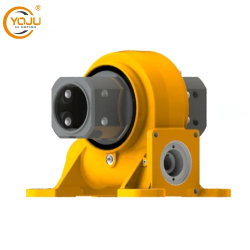
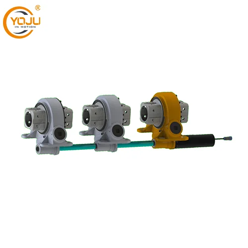
A slewing drive is a compact and highly efficient mechanical device designed to rotate heavy loads with precision. It is often used in applications where accurate tracking and positioning are essential, such as in solar tracking systems. Solar trackers equipped with slewing drives follow the sun' s trajectory throughout the day, enhancing the energy capture of solar panels. In this blog post, YOJU will share the manufacturing process of slewing drives for solar trackers, detailing the critical steps, materials, and techniques involved.
1. Design and Engineering Phase
1.1 Requirements and Specifications
The first stage involves defining the technical requirements based on the tracker design. The key parameters include:
- Torque capacity to rotate the solar panel system against wind loads.
- Backlash control for precise tracking.
- Gear ratio for smooth and efficient rotation.
- Corrosion resistance, as slewing drives operate outdoors.
- Sealing and lubrication systems to ensure low maintenance in harsh environments.
The design phase includes 3D modeling using CAD software, where engineers develop virtual prototypes. Finite Element Analysis (FEA) is employed to ensure structural integrity under loads such as wind, gravity, and temperature variations.
2. Material Selection and Preparation
2.1 Choice of Materials
The materials used in slewing drives are selected to meet the requirements for strength, wear resistance, and environmental durability. Typical materials include:
- Gears and raceways: High-strength alloy steel (e.g., 42CrMo) for wear resistance.
- Housings: Cast iron or aluminum alloy, depending on weight and corrosion resistance needs.
- Bearings: Chromium steel or stainless steel to withstand axial and radial loads.
- Seals: Nitrile or Viton for UV resistance and water sealing.
2.2 Raw Material Preparation
The selected materials are cut and prepared for machining. Bars, billets, and castings are subjected to processes like shot blasting and annealing to remove surface impurities and relieve internal stresses.
3. Machining of Components
3.1 Gear Machining
- CNC turning is used to shape the gear blanks to the desired dimensions.
- Gear hobbing or gear shaping creates the teeth profiles with precise geometry.
- Honing and grinding are performed to achieve tight tolerances and low surface roughness, ensuring smooth meshing with the worm or spur gear in the slewing drive.
3.2 Housing Manufacturing
- The housing is either cast or machined from solid blocks. If casting is used, the raw casting undergoes CNC milling to refine its dimensions.
- Threaded holes for bolts and mounting points are created through tapping and drilling operations.
3.3 Bearing Assembly Preparation
- Bearings are precision-ground to ensure low friction and tight tolerances.
- Raceways are machined into the housing or the slewing ring, forming the surface where the bearings will roll.
4. Heat Treatment
Heat treatment is a crucial step to enhance the mechanical properties of the slewing drive components, especially the gears and raceways.
- Carburizing or nitriding is used to harden the gear teeth and raceways, providing high wear resistance.
- Quenching is applied to improve toughness, followed by tempering to reduce brittleness and relieve stresses induced during quenching.
5. Surface Treatment and Coating
As slewing drives are exposed to harsh outdoor conditions, surface treatment is essential to prevent corrosion. Common methods include:
- Phosphating: Provides a primer layer for better paint adhesion.
- Electrophoretic painting (e-coating) or powder coating: Adds a protective coating that resists UV radiation, corrosion, and weathering.
- Zinc plating or hot-dip galvanizing: Offers additional corrosion resistance, especially for components used in coastal or humid environments.

6. Assembly Process
The assembly process is carried out in clean, controlled environments to prevent contamination. The key steps include:
6.1 Pre-Assembly Inspection
Each component is inspected for dimensional accuracy and surface quality. Non-destructive testing methods like ultrasonic testing (UT) or magnetic particle inspection (MPI) are used to detect any internal defects in critical components.
6.2 Bearing and Gear Assembly
- Bearings are installed into the raceways, and appropriate grease is applied to minimize friction and wear.
- The gear set (worm or spur) is integrated into the assembly with strict control over backlash to ensure smooth operation.
6.3 Seal Installation
Sealing rings and dust covers are installed to protect the internal components from dirt, dust, and moisture. A proper seal ensures long service life and reduces the need for frequent maintenance.
6.4 Final Assembly
The housing and other components are bolted together, and all fasteners are torqued to the specified values. Thread-locking compounds are often used to prevent loosening under vibration.
7. Testing and Quality Control
7.1 Functional Testing
Each slewing drive undergoes a series of functional tests to verify:
- Torque output: Ensuring the drive can generate the required torque without slippage.
- Backlash: Measuring the clearance between the gears to ensure precise tracking.
- Rotation smoothness: Ensuring smooth operation without excessive noise or vibration.
7.2 Environmental Testing
Slewing drives intended for solar trackers must perform reliably under varying weather conditions. Salt spray testing and temperature cycling tests are conducted to evaluate the drive's resistance to corrosion and thermal stress.
7.3 Load Testing
The slewing drive is subjected to simulated load conditions to confirm its structural integrity and mechanical performance under extreme scenarios.
8. Lubrication and Final Inspection
8.1 Lubrication
Proper lubrication is critical for the longevity of the slewing drive. High-performance greases or oils with additives for extreme pressure (EP) and corrosion protection are applied. Grease fittings are installed to allow for periodic re-lubrication during operation.
8.2 Final Inspection
A detailed inspection is performed to ensure compliance with all specifications. The checklist includes:
- Dimensional measurements with calipers and micrometers.
- Surface finish evaluation for gears and bearings.
- Torque tests on fasteners to confirm proper assembly.
9. Packaging and Shipping
After passing all quality control checks, the slewing drive is prepared for shipment.
- Protective covers are installed over critical surfaces such as the gear teeth.
- The drives are packed in shock-resistant crates or pallets, with desiccants included to prevent moisture accumulation during transit.
- Shipping documentation, including certificates of compliance and test reports, is prepared.
10. Installation and Maintenance Guidelines
Although not strictly part of the manufacturing process, manufacturers often provide installation guides and maintenance schedules. Key recommendations include:
- Correct alignment during installation to prevent premature wear.
- Periodic inspections for backlash, lubrication levels, and seal integrity.
- Replacement schedules for bearings and seals to ensure continuous operation.

Conclusion
The manufacturing process of slewing drives for solar trackers is a complex and precise operation involving design, material selection, machining, heat treatment, assembly, and rigorous testing. Each step plays a vital role in ensuring the drive performs reliably in harsh outdoor environments, contributing to the efficiency of solar tracking systems. As solar energy continues to grow, innovations in the manufacturing of slewing drives will further enhance the performance and longevity of these critical components.
https://www.enyoju.com/Manufacturing-Process-of-Slewing-Drive-for-Solar-Tracker.html
www.enyoju.com
YOJU

